Views#
The View layout provides flexible ways to visualize and interact with your machine and project. Each contained view offers a unique perspective—such as the 3D perspective or 2D cross-section—and can be considered one of the main aspects of the app, designed to help you monitor, analyze, and control your workflow more effectively. Up to four views are supported simultaneously, allowing you to tailor the workspace to your needs.
Abbreviations
📘 Throughout this page, you will see the following abbreviations being used:
3D: Three dimensional as in visualizing space, not the machine control type.
2D: Two dimensional as in visualizing flat without depth, not the machine control type.
General view control#
If you wish to focus on a specific view temporarily, double-tap any view to make it fill the whole layout. Double-tapping again will return to the previous layout.
Some views have more option buttons or more information that appears when tapping or interacting with the view, such as enabling/disabling colors in the cut-fill view.
The view layout can be edited with the Layout Editor
3D and 2D views#
The 3D and 2D views are used to visualize the operations the machine is currently doing through a virtual camera that can be panned and zoomed. They share some common features like, snap to tool point and hide machine parts.
Snap to tool point#
The 3D and 2D views have a snapping feature which you can use to snap the virtual camera onto the active tool point. This is useful feature if you lost track of where the machine is, or want the camera to follow the machine as it moves.
Some views always snap to the tool point when not panning the camera and others can activate the snapping by pressing the Snap button. This feature will snap onto the active tool point on the machine. When the camera is snapped to a tool point it will follow it as the machine moves.
Panning the camera will disengage the snapping if possible.
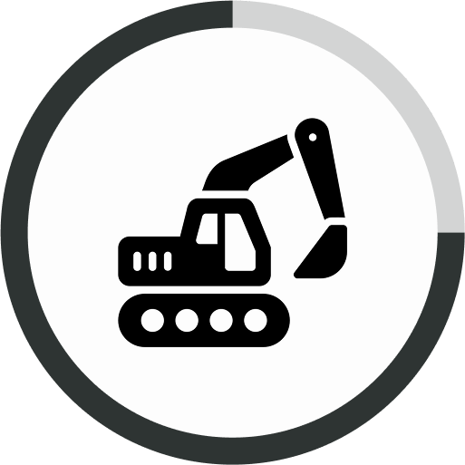
Hide/Show machine#
 In most views where the machine is visible, the extent of that visibility can be customized.
The button to control this appears when tapping or interacting with one of these views. Pressing the button gradually hide machine parts and eventually cycles back to showing the full machine. The ring around the button will reflect how much of the machine is currently showing. There are 5 levels of hiding the machine:
- Full machine
- No tracks/wheels
- Only stick and bucket
- Only bucket
- Only tool edge
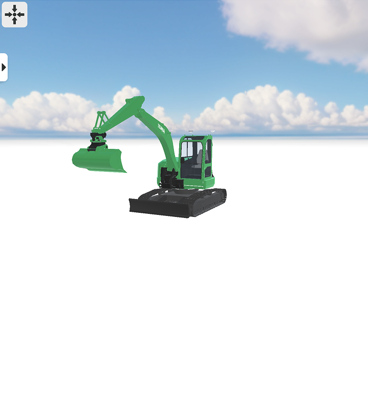
Perspective view#
 The Perspective view provides a virtual camera to view your machine and the project in 3D space. You can navigate the environment by using touch controls on the device running the app.
| Touch control | Action | Description |
|---|---|---|
| Drag one finger | Orbit the camera | Orbit the camera around a point of interest. If you have not used the Snap feature to snap to the tool point, you will orbit around the center of the camera's view. |
| Drag two fingers | Pan the camera | Moves the camera by placing a virtual pin through the environment where you placed your fingers. |
| Press two fingers and pinch or spread the fingers apart | Zooming in and out | Zoom the camera in if you pinch with your fingers. Zoom the camera out if you spread your fingers apart. |
| Press two fingers and drag + pinch or spread the fingers apart | Pan and zoom | Pan and zoom the camera at the same time. |
2D views#
The 2D views; cross-section, profile, top, and plan views are ways to view the project or machine in 2D. It provides a similar virtual camera to the perspective view, but the control scheme and behavior of 2D views function differently from its 3D counterpart.
| Touch control | Action | Description |
|---|---|---|
| Drag one finger. | Pan the camera | Moves the camera by placing a virtual pin through the environment where you placed your finger. |
| Press two fingers and pinch or spread the fingers apart | Zooming in and out | Zoom the camera in if you pinch with your fingers. Zoom the camera out if you spread your fingers apart. |
| Press two fingers and drag + pinch or spread the fingers apart | Pan and zoom | Pan and zoom the camera at the same time. |
Cross-section#
In this view you view a 2D slice of the project that is perpendicular to the forward direction of the tool. We call this the cross-section.
Any surface intersecting the cross-section is visible as a red line in this view, making this view useful for vertical referencing. In other views the same line is visible from other angles, this can help when understanding what the cross-section line is currently showing.
This view always snaps to the active tool point when not panning.
Profile#
Much like the cross-section view, the profile view also lets you view a 2D slice of the project. Here however, we view the tool from the left, perpendicular to the cross-section. We call this the profile.
Surfaces intersecting the profile are represented by a blue line, making this view useful for vertical referencing. The profile line can be seen in other views from other angles.
This view always snaps to the active tool point when not panning.
Top#
Much like the name suggests, the top view displays the project and machine viewed from above. Here both the cross-section lines and the profile lines can potentially be seen, intersecting with each other underneath the active tool point.
This view is optimal for horizontal referencing, as horizontal references from any angle will be visible here.
This view always snaps to the active tool point when not panning.
Plan#
This view is much like the top view, since the project is displayed from above. In this view surfaces are not visible to allow for a clearer overview of lines and points.
The machine is per default more hidden in this view, but can still be modified like the other views.
In this view it is possible to zoom out further and have large project areas in view all at once.
This view can be snapped to the active tool point, by pressing the snap button.
Info views#
These are views that only show various information in a intuitive manner. Most information is available in the info bar, but this allows full focus on a specifically interesting value.
Cut-fill view#
This view is the view version of the cut-fill widget. It displays the height of the active tool point. The color and the arrow indicates whether the references surface is above or below the tool point.
In this view the color can be disabled. To toggle the color of the view, tap inside the view and then press the button that appears in the top left corner of the view. This will toggle the color on or off. Without color the view has a neutral color that never changes.
Special views#
These are views not commonly used, but exists for marketing or development purposes.
Debug view#
This view shows a number of graphs displaying various performance-related information about the machine. This could be useful if the system is performing poorly or not acting as expected.
The graphs display the following:
- Frame rate - Performance of the app in frames per second
- IMU frequency - Frequency of received messages from each IMU
- GNSS frequency - Frequency of received messages from the GNSS module
- Delta position - Reflects positional changed in North, East and Altitude
- DOP values - Displays current HDOP, VDOP and PDOP values from the GNSS
Virtual camera view#
This view has number of virtual cameras to choose from. They all use perspective 3D and are attached to different parts of the machine.
Each camera can be angled, by dragging with one finger and zoomed by pinching. Change the current virtual camera by pressing the camera button in top right corner of the view.
The available cameras are:
- In front of cabin
- Inside cabin
- Left of the cabin
- On the underside of the boom
This has an overview of the most commonly used abbreviations used in the documentation.